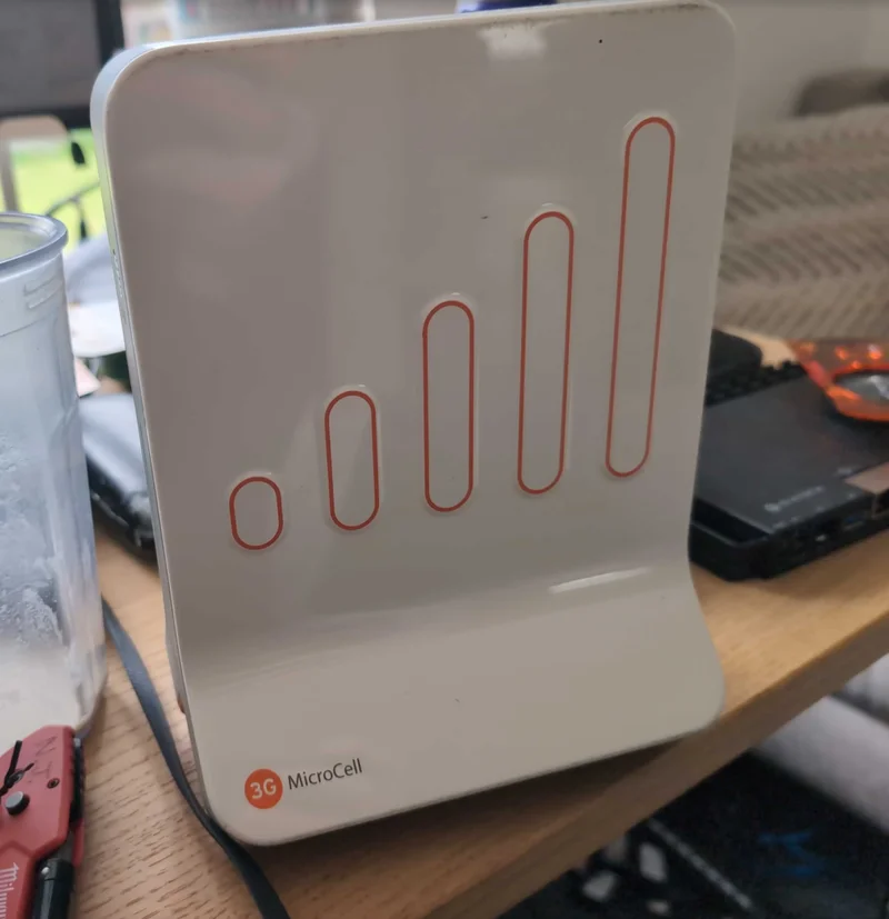
I wrote not to long ago ruing the fact I’d never done 3G, and despite the fact I own a bunch of 3G Small Cells, all purchased with the ambition of getting UMTS up and running, never having succeeded.
But recently on the Osmocom Discourse user Tempest has been playing with old AT&T 3G cells and building off the work of Neggles a a few others from several years ago. What’s awesome is that they got the dammed thing on the air!
So to eBay I went, and 4-6 weeks later I had myself a Cisco / AT&T branded DP-153-AT a UMTS femtocell capable of Band 8 and Band 2.
The thread explaining how to get these units online is long and a bit disjointed, but Tempest wrote up a much cleaner thread detailing the steps they’d gone through step by step to successfully transmit.
The Hardware Hacking Part
To make this work we need to get a JTAG debugger connected to the Picocom CPU on the device. Luckily for us there’s pads for JTAG, unluckily for us they’re not plain pin headers they’re just pads, and we’ve got to be pretty brutal with the case to get in there.
The unit also has a few little jumpers that pop open when you crack the case, which are there for tamper detection, but since the service this relies upon has been shut down for years, there’s no where it can phone home to, and there’s a script to reset it anyway.
So with a laptop in one hand a Dremel in the other, and the unit perched between my legs (safety first), I made the first incisions and cracked the case open, a spilled the tamper detecting jumpers everywhere – There was no going back now!
I’m no great solderer but eventually I soldered up all the pads required by the tutorial, and here is my first major screw up:
I’d soldered the wrong pads – the group of pads I should have soldered were about 20cm over to the right of these ones, which meant I had to remove them all and do it again in the correct location.
Tempest’s guide covers the soldering part really well, here’s my finished solder job
Once I’d soldered onto the CORRECT pads and the unit was talking JTAG and I was pretty chuffed with myself.
One thing that scared me was the tamper detection jumpers, there’s a block of little shorting jumpers like you’d use on a motherboard of old, that are pulled out if you open the case, spilling them everywhere. Luckily for us there’s a shell script in the root of the file system once we get in that clears and ignores the flag, but in my unit at least, the pads with the pin headers to jumper are top 2x jumpered, bottom one open in J15, where “top” is oriented with the text facing up (See the image below) – If you can’t be bothered doing this, that’s fine, you can clear it once we’re SSHed in but you’ll need to do it every time it reboots or setup a cronjob.
My second lesson though, was that while the unit will power itself from 5v and the lights will go on, it requires 12v, that’s why it comes with a 12v adapter. That’s also why it says “12v” on the unit. It requires 12 volts. Clearly all of these subtle clues were not enough information for me to comprehend, that for the unit to work, it needs 12v and I spent several hours fighting it before this dawned on me.
Software Flashing
So the goal of this whole thing is to get into the second CPU. There’s two CPUs on the board, a Ralink RT3050 which runs what is essentially a router, we can pop pretty easily, and behind it, a Picochip PC312 which runs the 3G NodeB stack which is the key to actually getting this thing ours.
Tempest’s breakthrough was getting the file-system of the Picochip modified so they could set the boot parameters to open up the debug serial port, and then from there get console into the unit.
I started with this approach, and I don’t know if I lifted a pad on my board for the Rx UART but no matter what I tried I couldn’t get serial input picked up onto the device, so I’ve taken a slightly different approach – Modify the filesystem to “pre” pop it so when it boots I don’t need to rely on the serial port.
I’m using a Tigard with all the pins populated (Yes, even VTGT) on the JTAG side and the voltage slider set to VTGT, I had to setup some basic deps I didn’t have:
sudo apt-get install -y openocd u-boot-s32-tools u-boot-tools
Connect the Tigard to our soldered pads, power on the device and run:
nick@amanaki:~/Documents/3G_Femto$ openocd -f openocd-dph153-tigard-adapted.cfg
Open On-Chip Debugger 0.12.0
Licensed under GNU GPL v2
For bug reports, read
http://openocd.org/doc/doxygen/bugs.html
Info : clock speed 500 kHz
Info : JTAG tap: pc302.cpu tap/device found: 0x07b763a9 (mfg: 0x1d4 (Picochip Designs Ltd), part: 0x7b76, ver: 0x0)
Info : found ARM1176
Info : pc302.cpu: hardware has 6 breakpoints, 2 watchpoints
Info : starting gdb server for pc302.cpu on 3333
Info : Listening on port 3333 for gdb connections
Info : JTAG tap: pc302.cpu tap/device found: 0x07b763a9 (mfg: 0x1d4 (Picochip Designs Ltd), part: 0x7b76, ver: 0x0)
Info : found ARM1176
Warn : pc302.cpu: ran after reset and before halt ...
target halted in ARM state due to debug-request, current mode: Supervisor
cpsr: 0x200001d3 pc: 0x0601103c
target halted in ARM state due to breakpoint, current mode: Supervisor
cpsr: 0x200001d3 pc: 0x06011004
Info : Listening on port 6666 for tcl connections
Info : Listening on port 4444 for telnet connections
It’ll probably crash a bunch of times, this is just a timing thing, plug in the unit, wait a few Mississippis and then fire up the openocd command and if you’re lucky it’ll find the Picochip and listen on 4444 for Telnet.
Then I connected to the unit via telnet with: telnet localhost 4444 and backed up the OG filesystem:
halt
dump_image /tmp/rwstore_now.bin 0x40480000 0x380000
Now here’s where the modified version of the flash comes in, it’s the vanilla flash but backdoored to hell, there’s SSH enabled, known keys added and some backups in case that fails.
You can take a fork in the road here, if you want to just do what I did, here’s a copy of all my files in the filesystem, and the SSH public key and backdoored filesystem to flash, but there’s some scripts in there that show how the filesystem was modified if you’re interested.
Next clear the flash and write the modified version from the .zip file:
halt
arm11 memwrite burst disable
reset halt
flash erase_address 0x40480000 0x380000
flash write_image /tmp/rwmkfs.bin 0x40480000
Then read it back to check the checkum of the filesystem on the flash matches what I just made because I’m paranoid and did this about 5 times never sure what I was doing wrong:
reset halt
dump_image /tmp/verify.bin 0x40480000 0x40000
on host: cmp /tmp/verify.bin against the head of /tmp/rwmkfs.bin -> MATCH
reset run
Then I let it boot.
Now for some networking – The Picochip lives on a 192.168.157.x address that’s behind the Ralink chip, so you have to add a static route on your machine (and in my case router as the hNB-GW is on a different subnet), so I had to add:
ip route add 192.168.157.84/30 via 10.5.198.115 where 10.5.198.115 is the lab DHCP lease the unit’s Ralink chip got, and 192.168.157.84/30 is the IP of the Picochip behind the Ralink chip.
After this you should be able to ssh in with the provided private key:
ssh -i femto-ssh/femto_id_rsa \
-o KexAlgorithms=+diffie-hellman-group1-sha1 \
-o HostKeyAlgorithms=+ssh-rsa \
-o PubkeyAcceptedAlgorithms=+ssh-rsa \
-c aes128-cbc \
[email protected]
And with that, you should be in and root on the Picochip and able to start configuring it to talk to your Osmocom hNB-GW.
I’m publishing this as I work it out myself, but next week I’ll hopefully have more of a writeup on getting the unit synced for time and pointed at the Osmocom Home NodeB gateway so we can get this thing on the air as I work it out myself (I currently have this intermittently on the air at the moment so still working through the second phase).